| ::sfu>ensc>ramp>mpk>development | |||||||
|
Repository Documents Development Create Scenes Releases To-Do list Bugs reports FAQs |
Create your own sceneThere are many predefined scenes in current released, in both 2D and 3D environment, using different type of robots. You can also create your own scene with your own robots.Create your own .mpk fileThe following shows an example of .mpk file.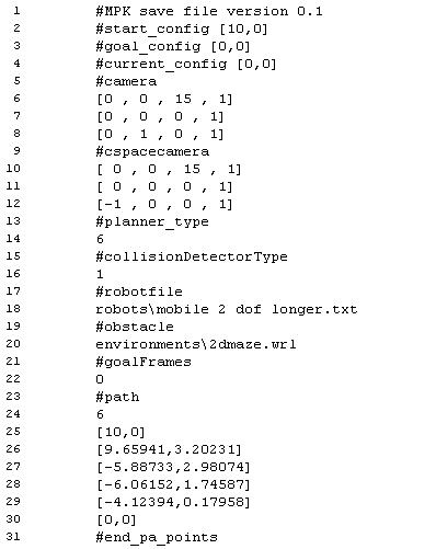
Create your own robotThe following shows an example of robot file.
The file should be self-explanatory. The links are VRML objects, and the joints are defined with DH parameters. The robot defined by the above file is shown in the following figure, where the joint frames and the tool frame are also shown. 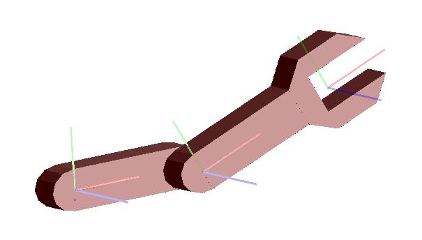
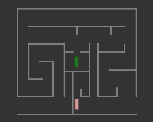
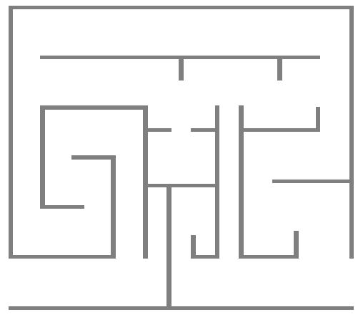
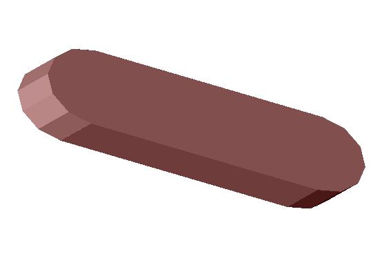
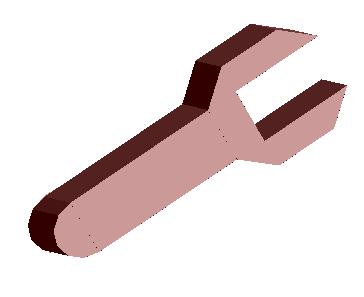
Create your own object modelsIn MPK, VRML model is used to define robot links and obstacles. For example, the following are objects used in previous files.
To create your own object (.WRL file) you need to use CAD software like Solidworkds. |
||||||
| Updated on May 10, 2007 by Zhenwang Yao . | |||||||
|
|
|
|